Ground Sample Distance: What GSD Does and Doesn't Tell You
Ground sample distance explained: what GSD measures, how off-nadir angle stretches it, and why the pixel size says nothing about where the pixel sits.
Summary
- Ground sample distance (GSD) is the distance on the ground between the centres of two neighbouring pixels. It comes from three numbers: detector width times orbit altitude, divided by focal length. For WorldView-2 that is 8 µm × 770 km ÷ 13.3 m = 0.46 m, which is the figure on the datasheet.
- GSD is quoted looking straight down and grows as the satellite looks sideways. WorldView-3’s 31 cm becomes 34 cm at 20° off-nadir and about 40 cm at 30°. The flat-ground shortcut for that stretch under-reads it by 10 to 20%.
- GSD says nothing about where a pixel sits on the Earth. That is positional accuracy, a separate figure: WorldView-3 is specified at under 3.5 m CE90 without ground control, refined Sentinel-2 at about 8 m at 95% confidence, Landsat Level-1 at 12 m radial RMSE.
- The same error is a different number of pixels at every GSD. A 3.5 m error is 12 pixels on a 30 cm image and a third of a pixel on Sentinel-2, which is why an overlay that looked fine at 10 m falls apart at 30 cm.
- Accuracy is made in processing, not in orbit. The elevation model, the camera-model refinement and any ground control decide it. Ask for GSD at nadir, the maximum off-nadir angle, and CE90 with and without control, and you have asked the right questions.
If you are comparing satellite imagery quotes you have probably noticed that every one of them leads with a pixel size, and that no two vendors seem to mean quite the same thing by it. Underneath that is a plainer question: does that number decide whether the imagery does the job? We should say up front that Geopera sells pixel size, and the smaller the pixel the more we charge, so we have an interest in you caring about it. This post is partly an argument against that interest. Ground sample distance is the number on the front of the spec sheet. The number that decides most jobs is further back, if it is there at all, and it is where the pixel actually sits.
What Ground Sample Distance Measures
Ground sample distance is the distance on the ground between the centres of two adjacent pixels. Point a telescope at the Earth from orbit and each detector element on the focal plane sees a small patch of ground. GSD is the spacing of those patches. It comes from three numbers and nothing else: the width of one detector element, the height of the orbit, and the focal length of the telescope. Multiply the first two and divide by the third.
WorldView-2 is a clean worked example because all three numbers are public. Its panchromatic detectors are 8 micrometres wide, it orbits at 770 km, and its telescope has a focal length of 13.3 m, per eoPortal’s mission summary. Eight millionths of a metre times 770,000 m, divided by 13.3, is 0.463 m. The datasheet says 0.46 m. That is the whole formula, and it is why the figure is called a sample distance and not a resolution. It is a spacing, decided by geometry, before a single photon is counted.
Resolution is a different thing. In optics it means the smallest separation at which two objects can still be told apart, and it depends on the aperture, the quality of the mirrors, the response of the detector, and how much the image smeared while the shutter was open. Engineers fold all of that into one curve, the modulation transfer function, and two sensors with identical GSD can sit on quite different curves. That is why 30 cm imagery from one satellite looks crisper than 30 cm from another. Aerial mapping has an old rule of thumb that the smallest feature you can reliably identify is two to three times the GSD, and it is only a rule of thumb. GSD is a spec you can compute from a datasheet. Resolution is a property you can only measure on the pixels.
So when a vendor says 30 cm-class they mean a GSD somewhere between about 29 and 34 cm, and they are telling you the spacing, not the sharpness. The pixel ladder in our high-resolution post shows what that spacing buys on a real scene, rung by rung. This post is about the other half.
One more thing hides inside the front-page figure. It is the panchromatic GSD. WorldView-3’s colour bands are collected at 1.24 m, four times coarser than its 31 cm panchromatic band, and the 31 cm colour image you receive is a pansharpened product: detail from the pan band, colour from the 1.24 m bands. The GSD on the file is real. The colour at that GSD is interpolated.
How Off-Nadir Angle Changes GSD
Every GSD on a datasheet is quoted at nadir, looking straight down. Satellites rarely look straight down, because a satellite that only imaged what passed directly beneath it would take weeks to come back over your site. Steering the camera sideways is what makes daily tasking possible, and it costs pixel size, in two ways at once.
Tilt the camera and the ground is further away, so every pixel grows by the ratio of slant range to altitude. Tilt it and the ground is also foreshortened in the direction you are looking, the way a tiled floor looks compressed toward the far wall of a room, so pixels in that direction stretch by a second factor on top of the first. Across the look direction the pixel grows once. Along it, twice. The single figure vendors quote for an off-nadir angle is the geometric mean of the two, one number standing in for a rectangle.
The table below works the geometry for a 31 cm sensor at 617 km, WorldView-3’s altitude, including the curvature of the Earth. The check on it is the datasheet: Vantor quotes 34 cm at 20° off-nadir, and that is what the geometry gives.
| Off-nadir angle | Across the look | Along the look | Quoted GSD (mean) |
|---|---|---|---|
| 0° | 31 cm | 31 cm | 31 cm |
| 10° | 32 cm | 32 cm | 32 cm |
| 20° | 33 cm | 36 cm | 34 cm |
| 30° | 36 cm | 44 cm | 40 cm |
| 40° | 42 cm | 59 cm | 50 cm |
| 45° | 46 cm | 73 cm | 58 cm |
Two things follow. First, a tasking order that allows up to 30° off-nadir, which is a common ceiling, can deliver a 40 cm pixel from a 31 cm satellite, and the file will still be labelled 30 cm-class. If the pixel size matters, put the angle limit on the order. Second, one trap for anyone working this out themselves: the cheap formula, which divides the nadir GSD by the cosine of the off-nadir angle, treats the ground as flat. At 617 km the Earth curves away enough that a 20° tilt at the satellite meets the ground at 22°, and at 45° it meets it at 51°. The flat version under-reads the stretch by 10 to 20%, depending on the angle. That is small next to the errors in the next section, but it is the kind of small that becomes a discrepancy in a tender response.
Positional Accuracy: Where the Pixel Actually Sits
Everything so far is about the size of a pixel. None of it is about where the pixel is.
A satellite knows its own position from onboard GPS to a few centimetres and its pointing from star trackers to a few arcseconds, and it hands you that knowledge as a camera model, usually a set of rational polynomial coefficients. From 617 km up, one arcsecond of pointing error, a 3,600th of a degree, moves the whole image 3 m on the ground. That is why the raw, uncorrected geolocation of a very-high-resolution image is measured in metres, not centimetres, no matter how small the pixels are. WorldView-3’s datasheet puts it at under 3.5 m CE90 without ground control. SuperView Neo is specified at 4 m CE90 without control, and the older SuperView-1 at about 9.5 m. For the free missions, the Copernicus programme’s geometric refinement of Sentinel-2 brought expected absolute accuracy to about 8 m at 95% confidence, and USGS holds Landsat Level-1 Tier 1 scenes to within 12 m radial RMSE.
Those figures come in different metrics, which is the first thing to sort out when comparing them. CE90 is the radius of a circle, centred on the true position, that contains 90% of the measured points. RMSE is the root mean square of the errors. If the errors are roughly normal and the same in each direction, CE90 is about 1.5 times the radial RMSE, CE95 about 1.7 times, and LE90, the equivalent for heights, about 1.6 times the vertical RMSE. So Landsat’s 12 m RMSE is roughly 18 m CE90, and Sentinel-2’s 8 m at 95% is roughly 7 m CE90. The ASPRS positional accuracy standard, revised in 2023, dropped the confidence-level figures and reports RMSE alone, so expect to convert whichever way your tender was written.
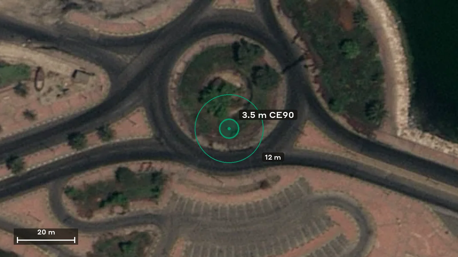
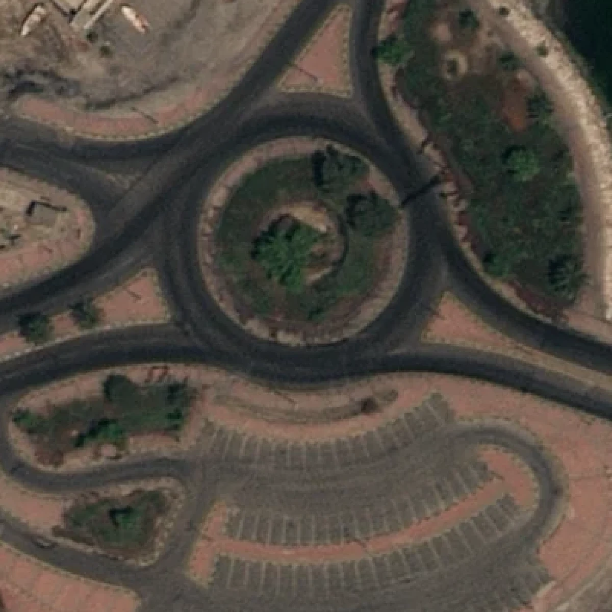
The figure below draws those numbers at true scale on real 30 cm pixels. The scene is 120 m of Darin, on Tarout Island in Saudi Arabia, from a Beijing-3N capture we processed in 2023, shown at three screen pixels per native pixel with no smoothing. The circle is the radius within which the true position of the centre dot lies, at each accuracy level. The parking bays at the bottom of the frame are about 5 m long, for scale.
 1 m · ground controlled
 1.0 m radius is 3.3 pixels at 0.3 m. Roughly what good ground control buys from a 30 cm sensor. The circle is smaller than a car.
The point of the figure is the readout under it. A 3.5 m error is 12 pixels at 30 cm and a third of a pixel at 10 m. A 12 m error is 40 pixels at 30 cm and barely one at 30 m. The error in metres does not change when the pixels shrink. What changes is how many pixels it is, and whether anyone notices.
| Positional error | At 30 cm | At 50 cm | At 1 m | At 10 m |
|---|---|---|---|---|
| 1 m | 3.3 px | 2 px | 1 px | 0.1 px |
| 3.5 m | 12 px | 7 px | 3.5 px | 0.35 px |
| 8 m | 27 px | 16 px | 8 px | 0.8 px |
| 12 m | 40 px | 24 px | 12 px | 1.2 px |
It would be easy to read that table as an argument that coarse imagery is more accurate. It is closer to the opposite. The 30 cm image is usually the more accurate one in metres. But nobody overlays a cadastre on a 10 m image, and everybody overlays one on a 30 cm image, so the fine pixel raises the stakes on a number the fine pixel does not control. A 3 m offset that was invisible for a decade of Sentinel-2 work becomes a fence line running through the neighbour’s house the first time the same team buys 30 cm.
Accuracy Is Made in Processing, Not in Orbit
The 3.5 m figure is where the satellite leaves you. Where you end up depends on what happens next, and three things decide it.
The first is terrain. A raw image places each pixel where the line of sight would meet a smooth reference surface, and real ground is not smooth. Anything above or below that surface is displaced sideways in the image, in the direction away from the satellite, by an amount that grows with the height and with the viewing angle. Orthorectification undoes that displacement using an elevation model, which means the ortho is exactly as good as the elevation model. Every metre the DEM is wrong moves the pixel by the tangent of the incidence angle. For the 617 km geometry above:
| Off-nadir angle | Shift per 10 m of DEM error | Flat-ground estimate |
|---|---|---|
| 10° | 1.9 m | 1.8 m |
| 20° | 4.0 m | 3.6 m |
| 30° | 6.6 m | 5.8 m |
| 45° | 12.3 m | 10.0 m |
Free global elevation models are 30 m grids that carry errors of several metres in ordinary terrain and far more in steep country, under forest, and anywhere a structure exists that the model has never heard of. The Three Gorges Dam incident of 2019 is the famous case: a 185 m concrete wall absent from the elevation model, orthorectified as if it were river, and a viral panic about a dam that was never bending. Nothing in that image had a bad GSD.
The second is the camera model itself. The rational polynomial coefficients that ship with a scene carry a small, mostly constant bias, and a handful of surveyed ground control points is enough to measure and remove it. A published test on WorldView-2 over a well-surveyed site brought planimetric error to 0.56 m RMSE with GCP-refined coefficients, from a raw figure of several metres. That is the difference between a product you can overlay on design drawings and one you cannot, and it is bought with survey points, not with a sharper satellite.
The third is relative accuracy, which is a different question from absolute accuracy and often the one that matters. If you are comparing two dates, you do not much care whether both images sit 3 m north-east of the truth. You care that they sit in the same place as each other, because a change detection algorithm reads a one-pixel misalignment as the edge of every building having moved. Sub-pixel co-registration between dates is the standard, and it is achievable with tie points even when absolute accuracy is loose.
Two traps from our own work belong here, because we paid for them. Comparing images taken from different orbits over steep terrain produces phantom shifts of several metres, because whatever error the elevation model has gets projected in a different direction at each viewing angle, and the difference between the two projections looks exactly like motion. We hit this measuring an ice mass in Nepal, and the fix was same-orbit pairs only. The other is vertical datum, and we lost a week to it: an elevation model in ellipsoidal heights and a survey in orthometric heights disagree by tens of metres in most of the world, which orthorectification duly turns into a horizontal shift. If your ortho is off by a suspiciously constant amount in one direction, check the datum before anything else.
Which Number Do You Need?
Most imagery jobs care about one of the two numbers far more than the other, and buying for the wrong one is the common mistake. The pairs below are the ones we see most.
| Task | GSD that does the job | Accuracy that matters | What to ask for |
|---|---|---|---|
| Counting vehicles, plant, stockpiles | 30 to 50 cm | Loose; a few metres is fine | Nadir GSD and maximum off-nadir |
| Site layout, disturbance footprints, progress | 50 cm to 1 m | Absolute, 1 to 3 m | CE90 without ground control |
| Overlay on cadastre, as-builts, designs | 30 to 50 cm | Absolute, under 1 m, needs control | CE90 with GCPs, and the check report |
| Change between dates | Any, same sensor | Relative, sub-pixel | Co-registration RMSE between dates |
| Vegetation, land cover, catchments | 10 m, free | Absolute, about a pixel | Nothing beyond the mission spec |
The first row is where most of the 30 cm money goes, and it barely needs an accuracy figure at all: a haul truck is a haul truck 3 m from where it should be. The third row is where the same 30 cm imagery needs survey control to earn its price. The fourth is where a 3 m sensor with a good co-registration beats a 30 cm sensor with a bad one, every time.
What to Write on the Order
A tender or an order that asks for the right numbers is short. It states the GSD at nadir and the maximum off-nadir angle you will accept, because at 30° your 31 cm is 40 cm. It names the accuracy figure in one metric, CE90 or RMSE, with its conditions: with or without ground control, and against which elevation model. It gives the vertical datum. And it asks for the geometric check, the list of points the delivered image was tested against and the residual at each, because a stated accuracy is a promise until someone has measured it against points on the ground. If you can supply survey points or a site DEM, say so on the order, since that is what moves the absolute figure from metres to decimetres. The buyer’s guide covers the rest of the order, licence included.
How Geopera Handles Geometry
Every order we deliver is orthorectified, using our own elevation models or the DEM and ground control you supply, and tie-point aligned so that scenes from different sensors and dates sit on one grid. Orthorectification is one stage of the Legato process, and the run only closes as Legato-processed if the automated geometry check passes; if it does not, the order routes to manual review rather than shipping. Each satellite’s sensor page lists its accuracy with suitable ground control alongside its GSD, and every result in Pera Portal shows its pixel size and capture date before you commit to anything.
If you would rather test the geometry on your own ground than take the table above on trust, you can apply for a processed sample over your site. We review applications and talk through the use case first, partly to make sure you are buying for the number that matters.
Frequently Asked Questions
What is ground sampling distance?
Ground sampling distance, or ground sample distance (GSD), is the distance on the ground between the centres of two adjacent pixels in an image. A 30 cm GSD means each pixel spans 30 cm of ground. It is set by the sensor’s detector width, orbit altitude and focal length, and is quoted at nadir, looking straight down.
Is GSD the same as resolution?
No. GSD is the spacing of pixels on the ground, computed from the sensor geometry. Resolution is the smallest separation at which two objects can be told apart, and it also depends on optics, detector response and motion blur. Two sensors with the same 30 cm GSD can differ noticeably in sharpness.
How do you calculate ground sample distance?
Multiply the detector element width by the orbit altitude and divide by the focal length. For WorldView-2, 8 µm × 770 km ÷ 13.3 m gives 0.46 m, which matches its datasheet. Off-nadir, multiply by the ratio of slant range to altitude, and again by one over the cosine of the incidence angle in the look direction.
Does a smaller GSD mean higher accuracy?
No. Positional accuracy is set by the camera model, the elevation model used for orthorectification, and any ground control, not by pixel size. WorldView-3 has a 31 cm GSD and a raw accuracy of under 3.5 m CE90, which is about 12 pixels. Ground control can bring a 30 cm image to about half a metre.
What does CE90 mean in satellite imagery?
CE90 is circular error at 90%: the radius of a circle, centred on the true position, inside which 90% of measured points fall. WorldView-3 quotes under 3.5 m CE90 without ground control. For normally distributed errors CE90 is about 1.5 times the radial RMSE, so a 12 m RMSE is roughly 18 m CE90.
The pixel size is the number you pay for. The position is the number you inherit from whoever processed the image, and it can be checked with a handful of surveyed points and an afternoon. Buy the pixel size the job needs, then check where the pixels sit before you overlay anything on them.